CNC Press Brake Crowning Systems – Hydraulic vs. Mechanical Deflection Compensation for High-Precision Metal Bending
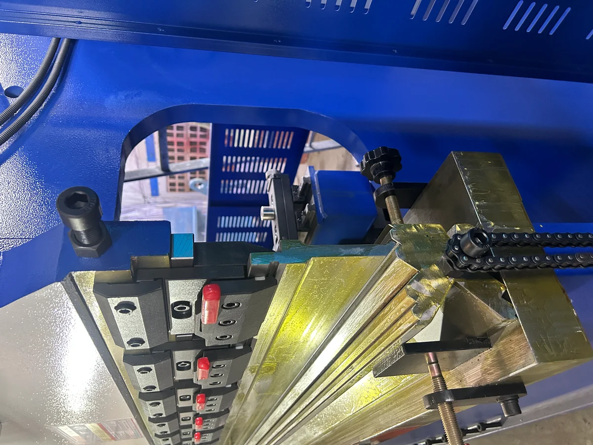
In precision sheet metal bending, frame deflection directly affects angle consistency across the bending length. This article examines the mechanical differences, PID feedback mechanisms, and ROI calculations between hydraulic and mechanical crowning systems.
In heavy-duty sheet metal fabrication, achieving a uniform bending angle across the entire length of a workpiece is a fundamental challenge. When a CNC press brake applies tonnage to a sheet of metal, an equal and opposite reaction force acts on the machine’s components. The upper beam deflects upward, while the lower bed deflects downward.
Without compensation, this physical deflection results in a wider bending angle in the center of the sheet compared to the ends—a defect commonly known in the industry as the “canoe effect”. To eliminate this error and ensure high-precision parts, modern press brakes employ advanced deflection compensation systems, commonly referred to as crowning systems.
Mechanical Deflection and the Need for Crowning
1. The Physics of Press Brake Deflection
When bending steel plates, the press brake frame acts as a structural C-frame assembly. Under load, the hydraulic cylinders at the side frames push the upper beam downward, but the middle of the beam has no direct vertical force supporting it. The beam bows upward in the center by fractions of a millimeter, while the bed bows downward.
The resulting deflection ($Y$) varies depending on the plate length, thickness, and material tensile strength. Even a tiny deflection of 0.1 mm in the center of the bed can cause a bending angle deviation of 1° to 2°, which is unacceptable for industries requiring high-tolerance components (such as aerospace, medical equipment, and precision enclosures).
2. Deflection and Crown Calculation
To offset this deflection, the crowning system must introduce an opposing curve (a “crown”) to the lower bed. This curve matches the deflection of the upper beam exactly, ensuring that the punch and die remain parallel throughout the entire bending stroke. The required compensation force ($F_c$) is determined by the bending force ($F$), the distance between frames ($L$), the material elasticity ($E$), and the moment of inertia ($I$) of the press brake beam:
Ymax = (5 × F × L3) / (384 × E × I)
Ymax: Maximum deflection (mm)
F: Applied bending force (N)
L: Distance between side frames (mm)
E, I: Material modulus & Beam inertia
Dynamic compensation ensures that the angle remains consistent, whether bending a short 500 mm plate in the center or a full-length 4000 mm plate.
Hydraulic Crowning Systems
1. Technical Explanation of the Hydraulic Mechanism
Hydraulic crowning systems feature a series of auxiliary cylinders embedded in the lower bed of the press brake. These cylinders are connected to a proportional hydraulic valve system controlled directly by the machine’s CNC unit (e.g., DELEM, Cybelec, or ESA).
When the operator enters the material parameters (thickness, length, tensile strength, and target angle) into the CNC controller, the software calculates the expected deflection. As the main cylinders descend, the proportional valve modulates hydraulic pressure to the bed cylinders, causing the lower bed to bow upward before the punch contacts the metal.
2. Advantages and Limitations
- Dynamic Adjustment: Hydraulic crowning can adjust compensation in real-time during the bending cycle. If pressure sensors detect that the material has a higher yield strength than entered, the PLC instantly increases hydraulic pressure to the bed cylinders.
- Maintenance Considerations: Over years of operation, hydraulic systems can experience seal wear, oil leaks, and changes in oil viscosity due to temperature fluctuations. A cold machine at 15°C may bend slightly differently than a warmed-up machine at 55°C unless the system includes automatic temperature compensation.
Mechanical (Wedge-Based) Crowning Systems
1. Technical Explanation of the Mechanical Mechanism
Mechanical crowning systems (often called wedge-based systems) use a series of opposing, high-precision steel wedges installed along the length of the lower bed. One set of wedges is fixed, while the opposing set is mounted on a sliding bar driven by a high-torque AC servo motor or a manual hand crank.
The wedges are CNC-machined with varying slopes. When the servo motor shifts the sliding bar horizontally, the wedges slide over each other, raising the center of the bed relative to the ends. This creates a highly accurate, symmetric parabolic curve.
2. Advantages and Limitations
- Exceptional Rigidity and Consistency: Because mechanical crowning relies on solid steel-on-steel contact, it is completely unaffected by hydraulic oil temperature, viscosity drift, or seal leaks. The height curve remains perfectly stable across thousands of cycles.
- Precision Wedges: The slope of each wedge is custom-engineered to match the deflection curve of the specific press brake model. This ensures a more uniform curve compared to hydraulic cylinders, which apply force at discrete points.
- No Dynamic Mid-Cycle Tuning: Unlike hydraulic crowning, mechanical crowning is set before the stroke begins and cannot adjust mid-bend if the sheet material thickness varies slightly within the same piece.
Comparison: Hydraulic vs. Mechanical Crowning
To help plant managers and procurement teams evaluate the best crowning setup for their operations, the table below compares the key technical parameters of both systems:
| Technical Parameter | Hydraulic Crowning System | Mechanical Crowning System |
|---|---|---|
| Actuation Method | Proportional hydraulic cylinders | AC servo motor driving sliding wedges |
| Response Control | Dynamic closed-loop (adjustable mid-bend) | Pre-set before bending stroke |
| Temperature Sensitivity | High (viscosity affects compensation) | Zero (steel wedges are stable) |
| Deflection Curve Matching | Approximated via discrete cylinders | Exact parabolic curve via custom wedges |
| Long-Term Wear Components | Hydraulic seals, solenoid valves, oil filters | Minimal (low-wear sliding surfaces) |
| Ideal Application | Varying material batches, thick plate bending | High-precision thin sheets, stainless steel |
Resolving B2B Pain Points: ROI and Productivity
For metal fabrication shops, investing in an automated crowning system (whether hydraulic or mechanical) yields clear financial paybacks.
1. Elimination of Test Bends and Setup Waste
On legacy press brakes without crowning, operators had to place paper shim stock under the lower die to adjust the height in the center manually. This manual shimming process was a trial-and-error method that took anywhere from 15 to 45 minutes per setup and wasted expensive test sheets.
With CNC-controlled crowning, the machine adjusts automatically in less than 2 seconds. For a shop running 5 setups a day, this saves up to 2 hours of labor daily, translating directly into increased machine capacity and higher throughput.
2. Reduction in Material Scrap Rates
Precision parts for automotive assemblies or architectural facades cannot tolerate angle variations. Scrap material, especially high-grade stainless steel or aluminum, is a major drag on profitability. By holding bending angle tolerances within ±0.3° across the entire bed length, RAXMEK crowning systems reduce scrap rates by up to 90%, saving thousands of dollars in raw materials annually.
Technical Consultation and Engineering Support
At RAXMEK, we engineer our press brakes to withstand decades of high-volume industrial use. Our gantry frames are welded, annealed, and machined to eliminate structural stress and ensure long-term structural rigidity.
If you are looking to upgrade your bending capabilities or need advice on configuring a custom press brake setup, our engineering team is here to assist you. We provide:
- Application Analysis: Helping you choose between hydraulic and mechanical crowning based on your material mix and tolerances.
- Material Test Bending: Send us your drawings and steel samples, and we will perform test bends, providing detailed cycle times, springback analysis, and angle readouts.
- Detailed Technical Quotations: Transparent, detailed B2B proposals covering tonnage, backgauge options, crowning configurations, and quick-change tooling.
Contact RAXMEK today to consult with our engineers and find the ideal configuration to optimize your metal fabrication process.
الموارد ذات الصلة
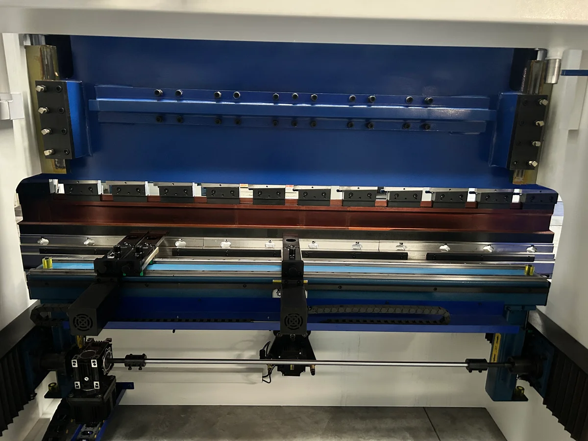
CNC Press Brake Backgauge Systems – Comparing Multi-Axis (X, R, Z1, Z2, X1, X2) Drive Configurations and Their Impact on Bending Accuracy
A deep dive into press brake backgauge axes, drive kinematics, and linear transmission systems. Learn how multi-axis (X, R, Z1, Z2, X1, X2) setups improve production speed...
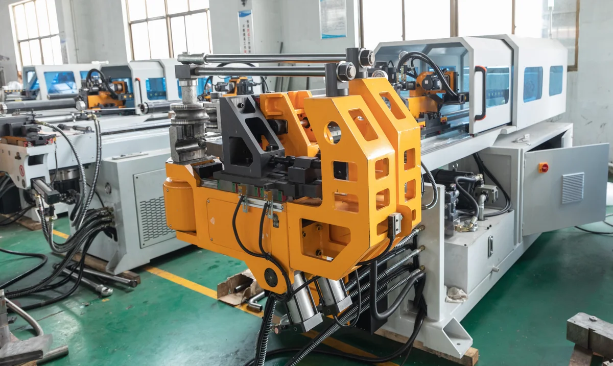
Mandrel Selection and Placement Kinematics – Preventing Wrinkling, Ovality, and Wall Thinning in Thin-Walled Tube Bending
High-quality tube bending requires careful management of internal and external forces. This article explores mandrel types, wiper die settings, and mandrel insertion depth...
Punch-to-Die Clearance Kinematics in CNC Punching – Preventing Burr Formation, Tool Wear, and Frame Deflection
Selecting the correct clearance between the punch and die is critical for hole quality and tool life. This article explains the mechanics of metal shearing, clearance calculations...