CNC Press Brake Backgauge Systems – Comparing Multi-Axis (X, R, Z1, Z2, X1, X2) Drive Configurations and Their Impact on Bending Accuracy
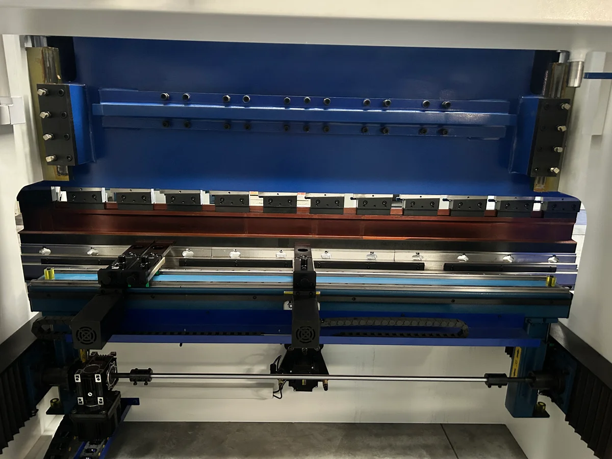
A deep dive into press brake backgauge axes, drive kinematics, and linear transmission systems. Learn how multi-axis (X, R, Z1, Z2, X1, X2) setups improve production speed and precision.
In the sheet metal fabrication industry, bending precision is determined by two main factors: the depth of punch penetration into the lower die (which controls the bend angle) and the position of the sheet relative to the bending line (which controls the flange length). While crowning and hydraulic systems manage the angle, the CNC backgauge system is solely responsible for flange length accuracy.
As parts grow more complex, requiring multiple bends of varying lengths and angles on a single workpiece, a standard single-axis backgauge quickly becomes a bottleneck. Modern manufacturing demands multi-axis, servo-driven backgauges that adjust position dynamically in milliseconds.
Defining the Backgauge Axes
To evaluate backgauge performance, it is essential to understand the coordinate system and the specific axes of motion. Each axis serves a distinct mechanical function during the bending process:
UPPER BEAM (Holds Punch)
BENDING LINE (Plate Bends Here)
LOWER BED (Holds Die)
- X-Axis (Depth): Controls the forward and backward movement of the backgauge fingers. This determines the flange length of the bend. It is the most critical axis for general accuracy.
- R-Axis (Height): Controls the vertical movement of the backgauge bar or fingers. When using dies of different heights, or when a bend creates a downward-sloping flange, the backgauge must raise or lower to support the sheet flatly.
- Z1 and Z2 Axes (Lateral Positioning): Control the independent left-to-right movement of the individual backgauge fingers. This is crucial when bending wide sheets, then transitioning to narrow sheets, or when performing off-center bending.
- X1 and X2 / R1 and R2 (Independent Multi-Axis): In advanced configurations, the backgauge fingers can move independently forward and backward (X1, X2) or up and down (R1, R2). This allows for taper bending (bending at an angle relative to the sheet edge) without manual fixtures.
Mechanical Kinematics and Drive Systems
1. Ball Screws vs. Linear Guides
To achieve high positioning accuracy and repeatability, the rotary motion of the servo motor must be translated into linear motion with minimal mechanical backlash.
Premium backgauge systems utilize high-precision recirculating ball screws mounted on dual linear guide rails with runner blocks. Ball screws provide a low-friction drive with mechanical efficiency exceeding 90%, eliminating the positioning drift common in older rack-and-pinion or belt-driven designs.
2. AC Servo Drive Dynamics
Modern backgauge systems are powered by brushless AC servo motors equipped with absolute rotary encoders. These motors deliver high torque-to-weight ratios, enabling rapid acceleration and deceleration rates up to 1.5g.
In high-speed production environments, the backgauge must move at speeds of 300 mm/s to 500 mm/s to position itself before the upper beam completes its cycle. The absolute encoder reads the exact shaft position, providing feedback to the CNC controller at high frequencies to maintain positioning repeatability within ±0.02 mm.
Technical Comparison of Backgauge Configurations
Selecting the right backgauge configuration is a trade-off between machine flexibility and investment cost. The table below outlines the capabilities of standard configurations:
| Configuration | Supported Axes | Geometry Capability | Ideal Production Environment |
|---|---|---|---|
| 2-Axis | X, R | Simple rectangular parts, single-setup bends | Small workshops, standard brackets |
| 4-Axis | X, R, Z1, Z2 | Step bending, varying sheet widths, multi-stage setups | General fabrication, medium-sized shops |
| 5-Axis | X, R, Z1, Z2, Delta X | Slight angular bending, unequal flange depths | Specialized enclosures, automotive parts |
| 6-Axis | X1, X2, R1, R2, Z1, Z2 | True taper bending, complex multi-stage parts | Advanced contract manufacturing, aerospace |
B2B Operational Impact and ROI
For contract manufacturers and high-volume fabrication plants, upgrading to a multi-axis CNC backgauge system directly impacts the bottom line.
1. Multi-Stage Bending (Single Setup)
With a multi-axis backgauge (e.g., 4-axis X-R-Z1-Z2), an operator can perform a sequence of different bends on a single sheet metal part in a single handling. The backgauge fingers adjust position between each stroke:
- Stroke 1: Fingers spread wide (Z1/Z2) for a wide initial bend.
- Stroke 2: Fingers move closer together and raise (R) to gauge off a pre-bent flange.
- Stroke 3: Fingers move forward (X) for a narrow return flange.
Without multi-axis control, the operator would have to bend a batch of parts at one station, change the machine setup, and run the batch again for the second bend. This batch-processing method increases material handling, raises the risk of damage, and increases total cycle time by up to 300%.
2. Eliminating Manual Fixturing for Tapers
Bending tapered parts (where the bend line is not parallel to the sheet edge) conventionally required operators to clamp custom metal alignment blocks to the lower die. This manual setup was time-consuming and prone to human error. A 6-axis backgauge (X1-X2-R1-R2-Z1-Z2) handles tapers automatically by positioning the fingers at different depths (e.g., X1 = 120 mm, X2 = 150 mm) before the punch descends, reducing setup time from 20 minutes to zero.
3. Investment Payback Analysis
Consider a fabrication plant processing 1,200 complex parts per month. Upgrading from a 2-axis backgauge to a 4-axis backgauge reduces handling and setup time by an average of 90 seconds per part:
Savings = 1,200 parts × 1.5 min/part = 30 hours of labor / month
At an average shop labor rate of $50/hour, this saves $1,500/month, paying back the multi-axis upgrade cost within the first year of operation.
Technical Consultation and Engineering Support
RAXMEK backgauges are built with high-rigidity structural steel frames, hard-chromed guide columns, and premium European linear transmission components. We ensure that our systems maintain their positioning accuracy under heavy, continuous production loads.
Our engineering team is available to help you configure the optimal backgauge system for your specific range of parts. We offer:
- Part Review: Send us your 3D CAD files, and we will simulate the bending sequence to identify the minimum number of backgauge axes required for efficient processing.
- On-Site and Remote Training: Ensuring your programmers and operators understand how to utilize multi-axis backgauges in DELEM/ESA software to minimize setup times.
- Custom Finger Design: Designing custom backgauge fingers or support tables for heavy or oversized sheets.
Contact RAXMEK today to speak with a technical expert and optimize your bending workflow.
Risorse Correlate
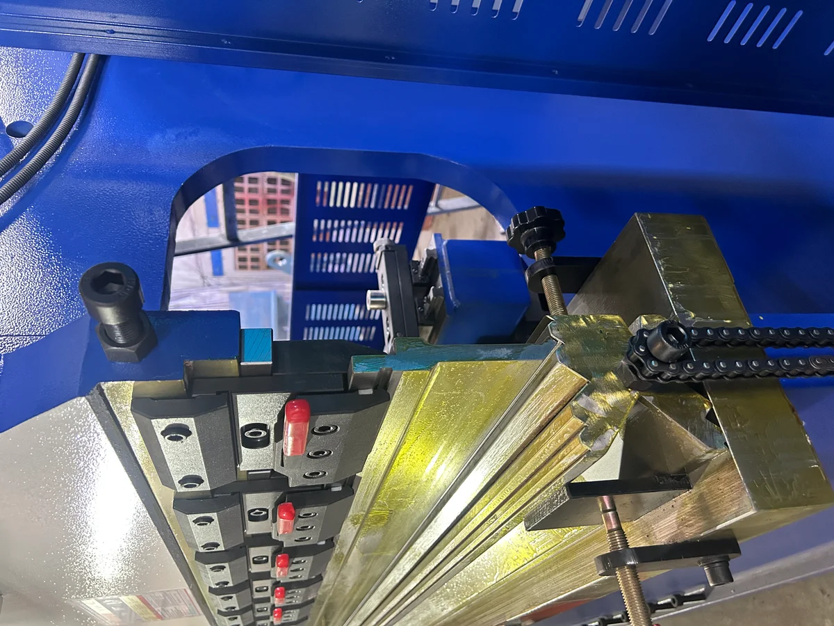
CNC Press Brake Crowning Systems – Hydraulic vs. Mechanical Deflection Compensation for High-Precision Metal Bending
In precision sheet metal bending, frame deflection directly affects angle consistency across the bending length. This article examines the mechanical differences, PID feedback...
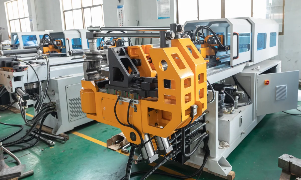
Mandrel Selection and Placement Kinematics – Preventing Wrinkling, Ovality, and Wall Thinning in Thin-Walled Tube Bending
High-quality tube bending requires careful management of internal and external forces. This article explores mandrel types, wiper die settings, and mandrel insertion depth...
Punch-to-Die Clearance Kinematics in CNC Punching – Preventing Burr Formation, Tool Wear, and Frame Deflection
Selecting the correct clearance between the punch and die is critical for hole quality and tool life. This article explains the mechanics of metal shearing, clearance calculations...