Hydraulic Valve Circuit Dynamics – Preventing Pressure Spikes, Cavitation, and Slow Cycle Times in Heavy Stamping
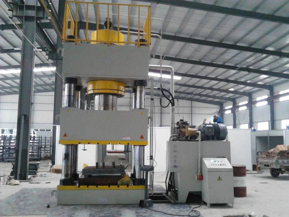
High-tonnage hydraulic pressing requires careful flow management to prevent circuit shocks. This technical analysis covers cavitation, pre-fill valves, and rapid decompression control.
Operating a high-tonnage hydraulic press machine involves managing extreme fluid energies. When compressing a workpiece under 500 tons of force, the hydraulic oil in the main cylinder is pressurized up to 31.5 MPa (4,500 PSI). At these pressures, hydraulic oil compresses volumetrically by about 1% to 1.5% depending on temperature, and the heavy steel frame stretches elastically.
This stored energy behaves like a compressed mechanical spring. If the control valves release this pressure instantly, the sudden escape of fluid creates a high-velocity shockwave. This shockwave is the leading cause of hydraulic line rupture, valve damage, structural weld cracks, and system cavitation.
The Physics of Cavitation and Hydraulic Shock
1. The Decompression Shockwave
When a valve opens abruptly to release high pressure, the oil rushes from the high-pressure chamber into the low-pressure return line. The speed of this pressure wave travels through the fluid at the speed of sound (approx. 1,200 m/s in hydraulic oil), generating a loud bang (hydraulic shock) and shaking the piping.
2. Cavitation During Decompression
As the high-velocity oil flows through the restricted valve opening, localized pressure drops below the oil’s vapor pressure. This causes dissolved air to bubble out of the fluid.
When these bubbles travel into higher pressure regions downstream, they collapse violently. The microscopic implosions generate localized temperatures up to 5000°C and high-velocity micro-jets that erode valve seats and eat away steel surfaces.
Hydraulic Solutions: Pre-Fill and Decompression Circuits
To manage high-speed stamping and drawing cycles safely, modern hydraulic presses incorporate advanced valve configurations.
1. Fast-Acting Pre-Fill Valves
During the fast-approach phase, the main ram descends under its own weight or is pushed by smaller high-speed cylinders. Because the main cylinder volume expands rapidly, oil must fill this chamber instantly to prevent vacuum formation (cavitation).
A large-bore pre-fill valve is mounted directly on top of the main cylinder, connecting it to an overhead gravity-fed reservoir. Under gravity, the pre-fill valve opens, allowing massive volumes of oil to flood the cylinder without pump assistance. When pressing begins, the pre-fill valve closes hydraulically, and high-pressure pumps take over.
2. Proportional Decompression Circuits
Before the main cylinder can retract, the hydraulic pressure must be bled off gradually. A decompression circuit uses a small, pilot-operated bypass valve in parallel with the main directional control valve.
The decompression valve opens first, letting a small volume of pressurized oil escape through a throttle orifice. Once pressure drops below a safe threshold (e.g., 2.0 MPa), the main pre-fill valve and directional valves open fully to retract the slide.
1. High Pressure Pressing
31.5 MPa (4,500 PSI)
The main cylinder is fully pressurized under load. The main spool and pre-fill valve are closed, locking in massive fluid energy.
2. Bypass Decompression
31.5 MPa → 2.0 MPa
A small pilot-operated decompression valve opens first. Stored oil pressure bleeds off gradually through a throttle orifice to prevent shockwaves.
3. Full Return Stroke
0.5 MPa (System Tank Return)
Once the pressure drops below the safe threshold, the main pre-fill and directional valves open fully, allowing a fast return stroke.
Circuit Configuration Performance
To guide production and maintenance managers, the table below highlights how circuit design choices affect machine performance:
| Hydraulic Design Feature | Standard Direct-Switch Circuit | RAXMEK Controlled Decompression Circuit |
|---|---|---|
| System Pressure Shock | High (valve shifting generates loud impact noise) | Near-Zero (controlled pressure ramp down) |
| Piping & Fitting Life | Reduced (frequent leaks due to vibration) | Extended (minimized fluid shockwaves) |
| Cycle Output Time | Long (slow approach to avoid cavitation) | Short (high-speed approach using pre-fill valves) |
| Oil Temperature Buildup | High (energy lost as heat during rapid drops) | Controlled (throttled flow limits heating) |
| Air Entrainment | High (vacuum suction draws air past seals) | None (system pressure remains positive) |
B2B Operational and Maintenance Strategy
For industrial stamping plants, maintaining hydraulic stability directly impacts floor productivity and tool lifecycle.
1. Oil Condition Monitoring
Cavitation and high-velocity oil shear degrade hydraulic fluid, breaking down its viscosity index and causing varnish formation on solenoid spools. Stamping presses should run active offline oil filtration systems (kidney loops) with a water-absorbing filter element. Maintaining fluid cleanliness to ISO 4406 16/14/11 standards reduces valve sticking failures by 80%.
2. Accumulator Pre-charge Audits
Many high-speed presses use nitrogen-filled bladder accumulators to store auxiliary fluid volume for fast cylinder movement. If the gas pre-charge pressure drops, the pump must work harder, cycle times increase, and pressure shocks intensify. Accumulator pressure should be audited every six months using a dedicated charging manifold.
Technical Consultation and Engineering Support
RAXMEK hydraulic presses are designed with integrated manifold blocks, cartridge logic valves, and programmable PLC decompression cycles to deliver smooth, high-speed performance under demanding production loads.
Our engineering team is ready to assist you in designing your press hydraulic system. We provide:
- Hydraulic Circuit Customization: Configuring custom pre-fill and dual-pump high/low flow circuits for specialized stamping speeds.
- Thermal Calculations: Analyzing your production duty cycles to design air- or water-cooled oil heat exchangers.
- System Integration Support: Providing full hydraulic schematics, valve cross-references, and PLC sequence logic.
Contact RAXMEK today to consult with a technical expert and improve your production reliability.
Похожие ресурсы
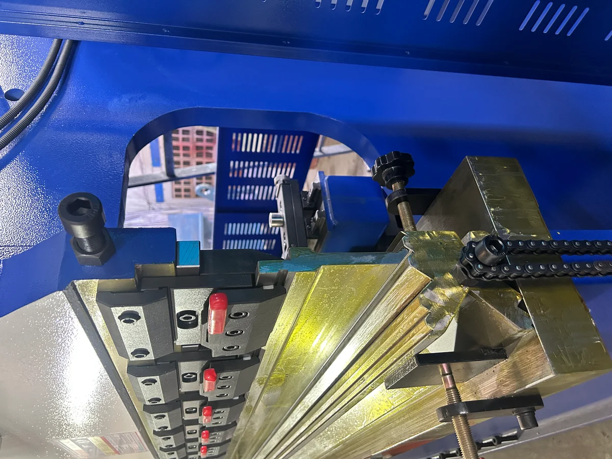
CNC Press Brake Crowning Systems – Hydraulic vs. Mechanical Deflection Compensation for High-Precision Metal Bending
In precision sheet metal bending, frame deflection directly affects angle consistency across the bending length. This article examines the mechanical differences, PID feedback...
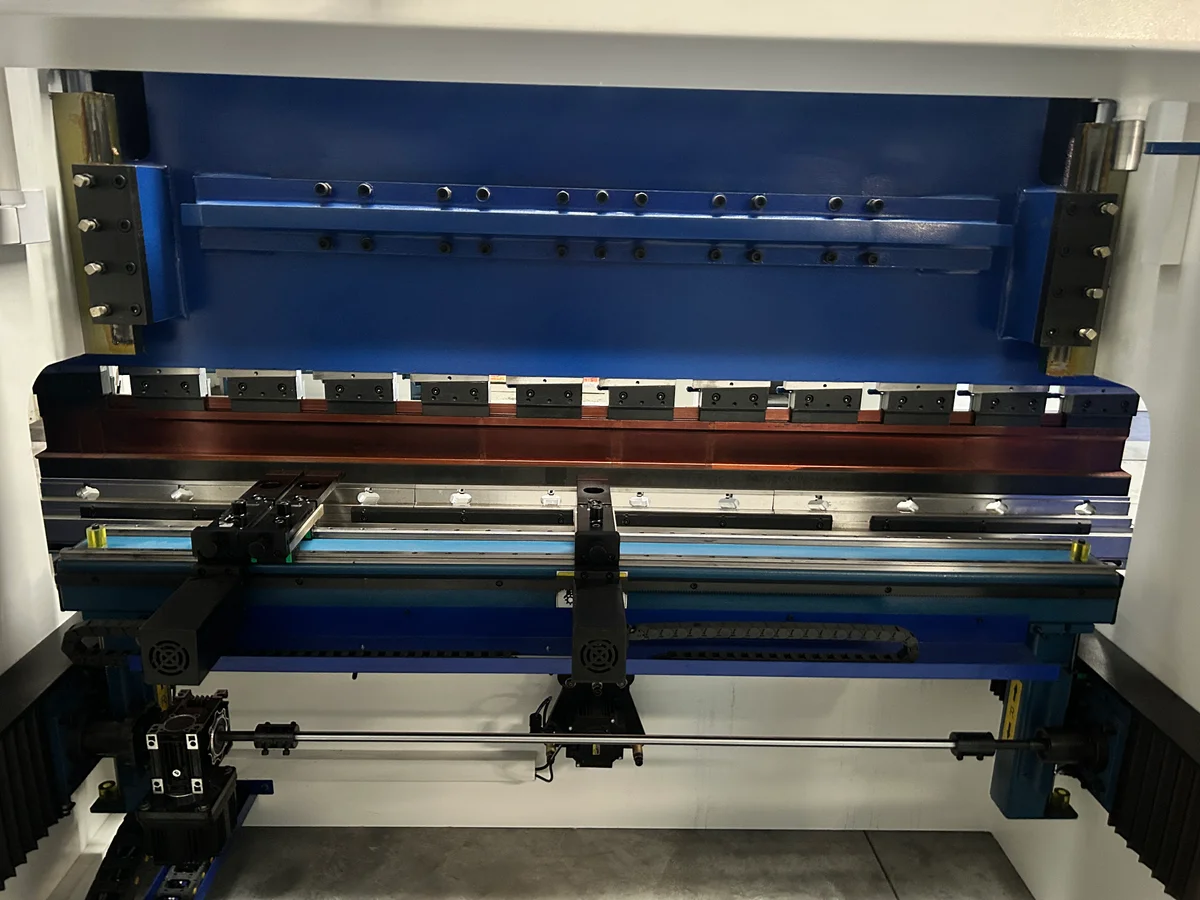
CNC Press Brake Backgauge Systems – Comparing Multi-Axis (X, R, Z1, Z2, X1, X2) Drive Configurations and Their Impact on Bending Accuracy
A deep dive into press brake backgauge axes, drive kinematics, and linear transmission systems. Learn how multi-axis (X, R, Z1, Z2, X1, X2) setups improve production speed...
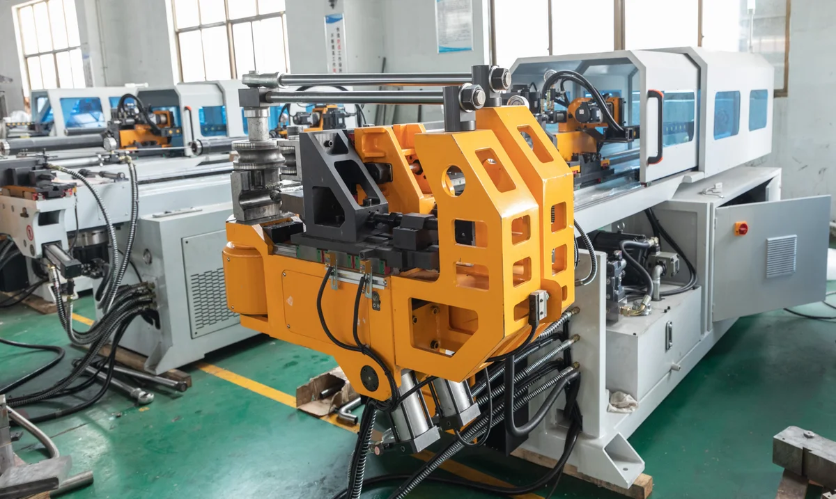
Mandrel Selection and Placement Kinematics – Preventing Wrinkling, Ovality, and Wall Thinning in Thin-Walled Tube Bending
High-quality tube bending requires careful management of internal and external forces. This article explores mandrel types, wiper die settings, and mandrel insertion depth...