Punch-to-Die Clearance Kinematics in CNC Punching – Preventing Burr Formation, Tool Wear, and Frame Deflection
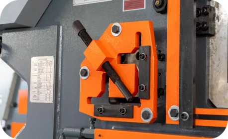
Selecting the correct clearance between the punch and die is critical for hole quality and tool life. This article explains the mechanics of metal shearing, clearance calculations, and how to troubleshoot punch wear.
In industrial metal punching, the quality of the finished hole and the lifespan of the tooling depend on a critical setting: the clearance between the punch and the die. Punch-to-die clearance is the difference in size between the outer diameter of the punch and the inner diameter of the die opening.
Improper clearance settings are the leading cause of burr formation, premature tooling wear, and unnecessary load on the machine’s hydraulic cylinder. For B2B manufacturing plants, maintaining optimal clearance is essential for keeping parts within tolerance and reducing tool replacement costs.
The Shearing Mechanism of Punching
When the punch contacts the sheet metal, it does not slice through the material like a knife. Instead, the process occurs in three distinct phases:
Elastic Deformation
The punch descends and contacts the sheet metal. The material is compressed and pushed into the die opening, stretching within its elastic limit.
Plastic Shearing
The punch penetrates deeper, exceeding the material’s yield strength. The metal flows plastically, forming a clean, burnished band on the hole wall.
Fracture & Ejection
Stresses exceed the ultimate tensile strength. Micro-cracks propagate from cutting edges, meet cleanly, and the slug is ejected downward.
- Elastic Deformation: The punch presses into the metal, pushing it into the die opening and stressing the material within its elastic limit.
- Plastic Shearing: The punch penetrates deeper, forcing the metal beyond its yield strength. The material flows plastically, creating a smooth “burnished” band on the hole wall.
- Fracture: As the material reaches its ultimate tensile strength, micro-cracks form at the cutting edges of both the punch and the die. These cracks propagate toward each other. When they meet, the slug fractures and is ejected through the die.
For a clean, straight-walled hole, the fracture lines starting from the punch edge and the die edge must meet exactly. If the clearance is incorrect, the fracture lines miss each other, causing secondary shearing, rough edges, and large burrs.
Calculating Optimal Clearance
The optimal total clearance ($C$) is expressed as a percentage of the material thickness ($t$) and varies based on the material’s shear strength and ductility. The general formula is:
C = t × fm
C: Total clearance (mm)
t: Material thickness (mm)
fm: Material clearance factor
The clearance factor ($f_m$) depends on the material grade:
- Aluminum (Soft/Ductile): $f_m = 0.08$ to $0.10$ (8% to 10% of thickness)
- Mild Carbon Steel: $f_m = 0.12$ to $0.15$ (12% to 15% of thickness)
- Stainless Steel (Hard/High Strength): $f_m = 0.18$ to $0.22$ (18% to 22% of thickness)
Using this formula, punching a 6.0 mm mild steel plate requires a total clearance of:
C = 6.0 mm × 0.15 = 0.90 mm
This means the die opening should be exactly 0.90 mm larger than the punch diameter.
Consequences of Incorrect Clearance
To help shop floor supervisors diagnose tooling issues, the table below outlines the mechanical consequences of incorrect clearance settings:
| Clearance Condition | Mechanical Symptoms & Effects | Finished Hole Quality |
|---|---|---|
| Too Tight (< 8% for steel) | High stripping force; double-fracture lines; extreme heat buildup; rapid punch dulling | Small burrs, excessive work-hardening on hole walls |
| Optimal (12% to 15% for steel) | Fracture lines meet cleanly; low stripping force; minimal tool wear; lowest cylinder load | Clean, straight walls; minimal burrs; flat slug |
| Too Loose (> 25% for steel) | Material drawn into die; excessive plastic deformation; high roll-over depth | Heavy, sharp burrs; tapered hole walls |
B2B Operational and Maintenance Strategy
Maintaining hole quality and minimizing downtime requires a structured tooling maintenance plan.
1. Stripping Force and Tool Lubrication
During the return stroke, the punch must be pulled back out of the sheet. The force required to pull it out is called the stripping force.
If the tool clearance is too tight, or if the tool is unlubricated, the metal clings to the punch, requiring high stripping force. This can bend thin sheets and cause the punch to chip. Implementing an automatic, pulse-lubrication system that sprays a light mist of lubricant onto the punch tip before each stroke reduces stripping friction and extends tool life by 50%.
2. Sharpening Thresholds
Operating a dull punch increases the required punching force, causes frame flexing, and produces heavy burrs. Tooling should be inspected regularly and sharpened (ground) as soon as the cutting edge develops a radius of 0.1 mm. Grinding off just 0.05 mm to 0.10 mm of the tool face restores the sharp edge, allowing the tool to be sharpened up to 10 times before replacement is needed.
Technical Consultation and Engineering Support
RAXMEK CNC punching machines and hydraulic ironworkers are engineered for heavy-duty industrial environments. We use high-precision guide systems to ensure perfect alignment between the punch holder and the die bed.
Our engineering team is ready to help you optimize your punching processes. We offer:
- Tooling Audits: Calculating optimal clearance charts for your specific range of material grades and thicknesses.
- Custom Punch Design: Engineering shaped tools (oblong, square, hexagonal, or multi-hole clusters) to match your parts.
- Tonnage Calculations: Calculating the required tonnage for large-hole or thick-plate punching to ensure you stay within safe machine limits.
Contact RAXMEK today to consult with our engineering support team and improve your punching efficiency.
Похожие ресурсы
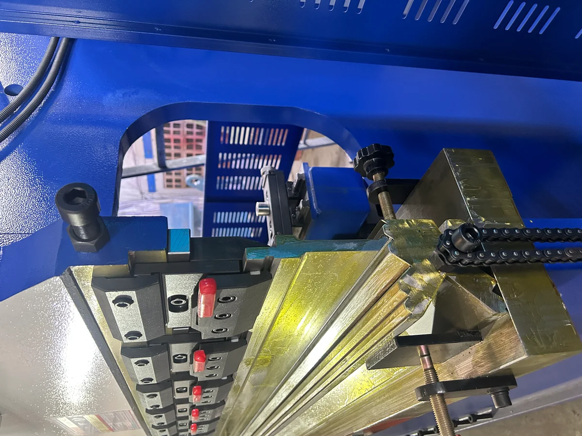
CNC Press Brake Crowning Systems – Hydraulic vs. Mechanical Deflection Compensation for High-Precision Metal Bending
In precision sheet metal bending, frame deflection directly affects angle consistency across the bending length. This article examines the mechanical differences, PID feedback...
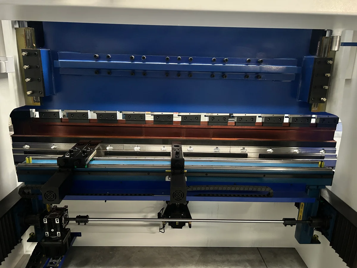
CNC Press Brake Backgauge Systems – Comparing Multi-Axis (X, R, Z1, Z2, X1, X2) Drive Configurations and Their Impact on Bending Accuracy
A deep dive into press brake backgauge axes, drive kinematics, and linear transmission systems. Learn how multi-axis (X, R, Z1, Z2, X1, X2) setups improve production speed...
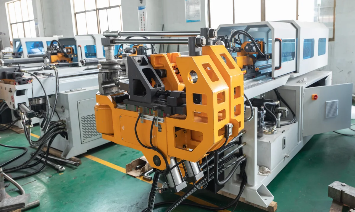
Mandrel Selection and Placement Kinematics – Preventing Wrinkling, Ovality, and Wall Thinning in Thin-Walled Tube Bending
High-quality tube bending requires careful management of internal and external forces. This article explores mandrel types, wiper die settings, and mandrel insertion depth...